
Safety-critical PCB design
BSPD Safety-Critical PCB Design
End-to-end development of a standalone, non-programmable Brake System Plausibility Device that protects an electric Formula Student race car by detecting unsafe braking and power-delivery conditions.
VALIDATED
Role
Hardware / Embedded Systems Engineer
Project
ESTACARS Formula Student - France
Period
September 2023 - January 2026
Problem
A Formula Student electric vehicle needs an independent safety system that continuously checks whether the driver's braking demand is consistent with the power delivered to the motors. If hard braking and excessive propulsion occur simultaneously, the device must open the Shutdown Circuit (SDC), causing the Accumulator Isolation Relays (AIRs) to open and isolate the HV battery from the vehicle. The inverter must then discharge the remaining energy stored in the high-voltage circuit, bringing the vehicle to a safe state.
The challenge was broader than detecting two thresholds. Formula Student rules require a standalone, non-programmable circuit supplied directly from the Low Voltage Master Switch. Brake pressure and DC-link current are System Critical Signals, so disconnections, shorts, and out-of-range behavior must also lead to a safe response. The circuit therefore had to combine precise analog measurement, deterministic timing, fault detection, and fail-safe shutdown logic without relying on software.
Core requirements
- Detect hard braking from a hydraulic pressure sensor while keeping the selected threshold below the wheel-locking condition and at or below 30 bar.
- Detect power delivery above 5 kW; at the vehicle's maximum tractive-system voltage of 404 V, this corresponds to approximately 12 A.
- Open the SDC when the braking and power conditions remain implausible, with the required persistence behavior implemented entirely in hardware.
- Detect open-circuit, short-to-ground, short-to-supply, and out-of-range sensor faults and drive the system to a safe state.
- Use only the minimum required interfaces and allow each sensor signal to be disconnected separately during technical inspection.
- Ensure that an unpowered or disconnected BSPD opens the SDC rather than allowing continued tractive-system operation.
Solution
I developed a dedicated analog BSPD PCBA around two independent physical measurements: an EPT3100 brake-pressure sensor and a LEM HASS 200-S Hall-effect current sensor. The board conditions both signals, compares them against adjustable safety thresholds, detects invalid sensor voltages, applies hardware timing, and controls a relay in the vehicle shutdown circuit.
The complete decision path is deterministic and non-programmable. Comparators implement the threshold decisions, wired logic combines the braking and current conditions, dedicated monitoring detects sensor faults, and the output stage keeps the relay energized only while the system is healthy. A detected fault removes relay power and opens the SDC.
Platform capabilities
- Dedicated 12 V and 5 V regulated supplies for the analog circuitry and sensors.
- Offset cancellation and approximately x70 amplification of the current-sensor signal.
- Adjustable brake-pressure and current thresholds with deliberate safety margin.
- Hardware plausibility logic requiring simultaneous braking and excessive current.
- Under-range and over-range monitoring for both safety-critical sensor signals.
- RC-based persistence and reset timing with a comparator-controlled shutdown request.
- Fail-safe relay output stage: loss of command or supply opens the shutdown circuit.
Method
Step 1 - Convert regulations into engineering requirements
I began by extracting the BSPD requirements primarily from the Formula Student Germany (FSG) 2025 rulebook, supplemented by the 2025 technical-inspection procedure. I converted these regulatory statements into measurable thresholds, timing constraints, electrical interfaces, fault cases, safe-state behavior, and evidence that the board would need to provide during scrutineering.
The safety function was then decomposed into sensing, signal conditioning, plausibility comparison, sensor-fault detection, deterministic timing, fail-safe shutdown, and regulated power-supply stages. This requirements-first architecture kept every schematic block traceable to a regulatory purpose.
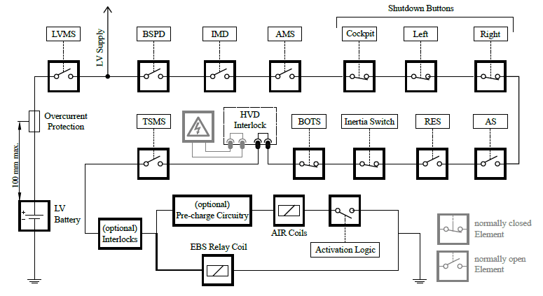
- Standalone, non-programmable implementation with only the necessary supply, sensor, and SDC interfaces.
- Safe-state behavior defined for loss or corruption of each system-critical sensor signal.
- Technical-inspection needs considered before schematic capture and connector selection.
Step 2 - Select and characterize the sensors
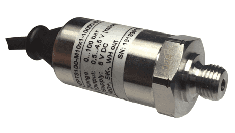
For braking demand, I selected an EPT3100 pressure sensor rated from 0 to 100 bar, with a 0.5-4.5 V output from a 5 V supply. Its sensitivity of 0.04 V/bar provides a direct relationship between hydraulic pressure and output voltage: the selected 20.75 bar threshold corresponds to approximately 1.33 V. Because the valid signal remains separated from both supply rails, open circuits, short circuits, and out-of-range conditions can also be detected by dedicated hardware.
For propulsion power, the BSPD uses DC-link current as the measured quantity. At the vehicle's maximum tractive-system voltage of 404 V, the 5 kW regulatory boundary corresponds to approximately 12.38 A. This maximum-voltage calculation gives the lowest current associated with 5 kW and therefore provides a conservative basis for a fixed hardware threshold across the operating-voltage range.
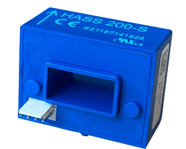
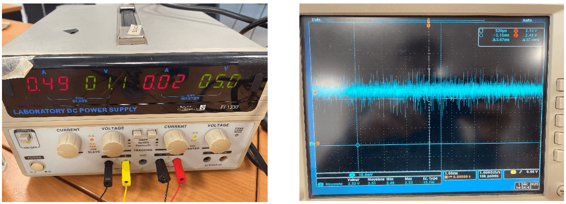
I selected the LEM HASS 200-S Hall-effect current sensor to cover the vehicle's full current range while providing electrically isolated measurement. Around the BSPD threshold, however, its output changes by only about 38 mV relative to its nominal 2.5 V zero-current reference. I measured the actual reference at approximately 2.49 V, establishing the offset and signal amplitude that the conditioning circuit in the following step needed to process.
Step 3 – Condition the current signal for reliable threshold detection
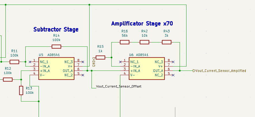
The HASS 200-S output is centred around a zero-current reference of approximately 2.49 V. At the 12.38 A regulatory boundary calculated in Step 2, the current-dependent variation is only about 38.7 mV. This small differential signal is not suitable for robust direct comparison because sensor offset, electrical noise, and component tolerances could become significant relative to the measured variation.
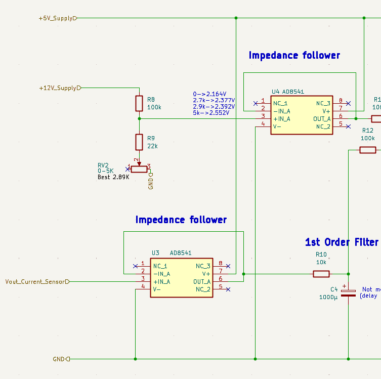
I buffered the sensor output and its calibrated zero-current reference to prevent loading and impedance interactions. A first-order filter attenuates high-frequency noise before the differential stage subtracts the zero-current offset. The remaining current-dependent signal is then amplified by approximately ×70, producing a voltage range that can be evaluated reliably by the comparator logic in Step 4.
An adjustable offset-calibration network compensates for the measured sensor reference and real component tolerances. This makes the conditioning stage calibratable without software while preserving a deterministic analog signal path.
Step 4 – Implement plausibility logic and sensor-fault diagnostics
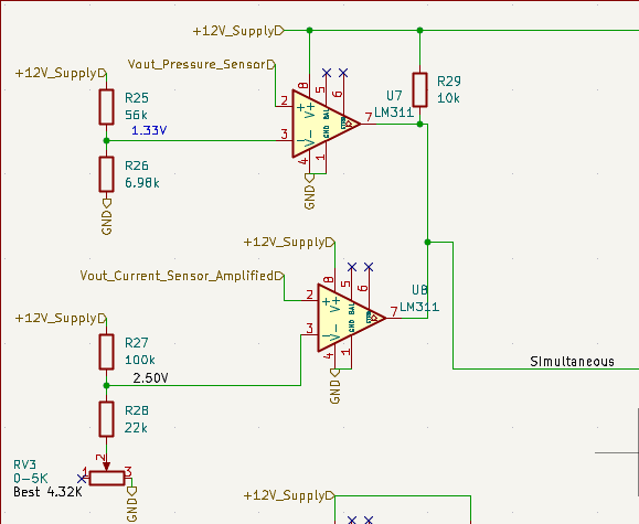
The conditioned sensor signals are converted into deterministic hardware decisions using LM311 comparators. The brake comparator trips at approximately 1.33 V, corresponding to 20.75 bar and remaining below the 30 bar regulatory limit. The amplified current channel is compared against a 2.50 V threshold, corresponding to approximately 11.52 A. This is deliberately below the 12.38 A associated with 5 kW at 404 V, providing a conservative detection margin for component and calibration tolerances.
The brake and current comparator outputs are combined using hardware AND logic. A plausibility condition is therefore asserted only when hard braking and excessive propulsion current occur simultaneously; braking or propulsion alone does not initiate a shutdown request. The resulting signal is passed to the timing circuit in Step 5, where the required persistence behavior is applied before opening the SDC.
Because brake pressure and DC-link current are System Critical Signals, a separate diagnostic path continuously monitors their electrical validity. Additional comparators detect outputs above or below predefined voltage windows, allowing shorts, disconnections, and implausible sensor behavior to be identified independently of the main plausibility decision. The detected sensor faults are combined through hardware OR logic and routed toward the fail-safe shutdown path.
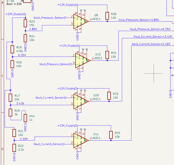
- Brake-sensor valid window monitored around its nominal 0.5-4.5 V output range.
- Current-sensor limits selected to detect disconnection, negative implausibility, and excessive positive output.
- A hardware OR stage combines detected failures and provides visible fault feedback on the PCB.
Step 5 – Implement 250 ms persistence timing and fail-safe SDC control
Formula Student regulations require the SDC to open within 500 ms after detecting simultaneous hard braking and excessive propulsion current. To provide sufficient margin below this maximum reaction time, I designed the analog timing stage for a nominal persistence delay of approximately 250 ms. This prevents very brief signal overlap from triggering the shutdown while ensuring that a sustained fault is acted upon within the regulatory limit.
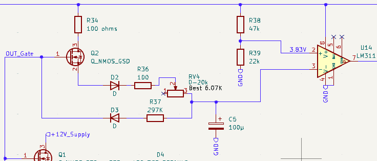
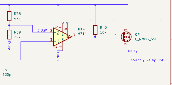
The plausibility signal from Step 4 controls Q2, which enables the charging path from the 12 V supply through R34, Q2, D2, R36, and RV4 to C5. While the fault remains active, C5 charges toward the LM311 comparator threshold. When its voltage reaches this threshold after approximately 250 ms, the timing stage produces a shutdown request. RV4 adjusts only this charging path, allowing the nominal shutdown delay to be calibrated against component and comparator-threshold tolerances at the calibration conditions.
When the plausibility condition disappears, C5 discharges through the separate D3-R37 path, which independently defines how the timing circuit resets. The reset timing must be verified experimentally across component tolerances, supply voltage, and temperature.
When the timing threshold is reached, the comparator and MOSFET output stage release the normally energized BSPD relay and open the SDC. A detected sensor fault, broken command path, or loss of BSPD power also releases the relay. This fail-safe architecture ensures that loss of the command or its supply cannot preserve tractive-system operation.
Step 6 – Finalize and simulate the regulated 12 V and 5 V supplies
After completing the sensing, conditioning, comparator, timing, and relay-control stages, I could determine the BSPD's actual supply requirements. These included the required voltage rails, expected loads, allowable voltage variation, regulator headroom, and the sensitivity of the analog thresholds to supply accuracy. I therefore finalized the power architecture only after defining the complete functional circuit.
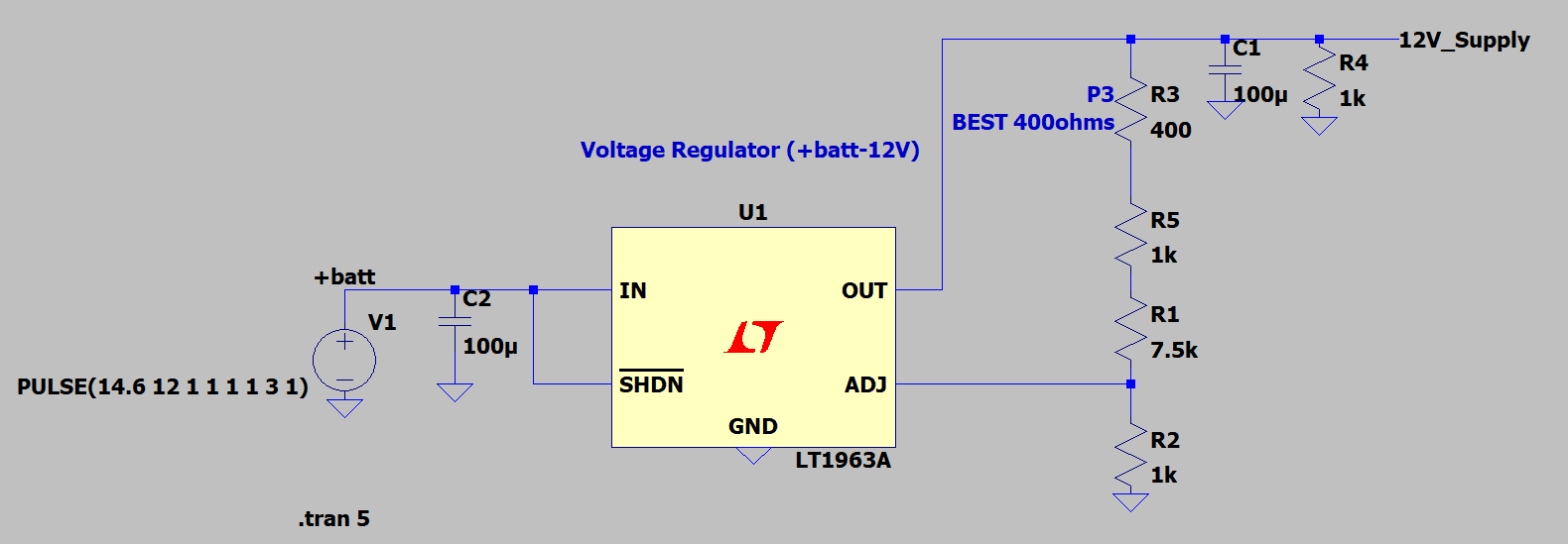
The vehicle's low-voltage system supplies the BSPD over an expected range from 12 V to 14.6 V. I selected an adjustable LT1963A regulator for the 12 V analog rail and an LT1117-5 for the regulated 5 V sensor supply. The adjustable 12 V stage allows the nominal output to be calibrated to account for regulator, feedback-resistor, and component tolerances.
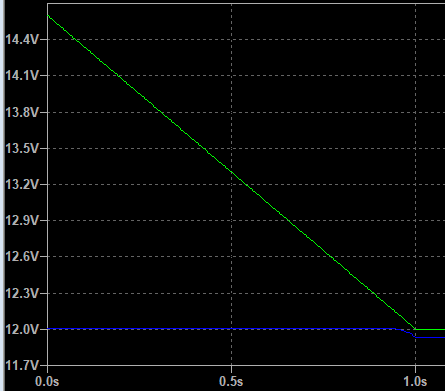
I evaluated the 12 V regulator in LTspice by sweeping its input from 14.6 V down to 12 V. With an input above approximately 12.35 V, the simulated output remained between 12.003 V and 12.006 V. Below this point, the regulator no longer has sufficient input-to-output headroom to maintain a regulated 12 V rail, identifying the dropout region that must be considered during vehicle operation.
I then transferred the simulated design into KiCad using the selected component values. The implementation includes input and output filtering, regulator-stability components, minimum-load resistors, and output adjustment. Physical testing must still confirm regulation under the real BSPD load, dropout behavior, thermal dissipation, supply transients, and worst-case component tolerances.
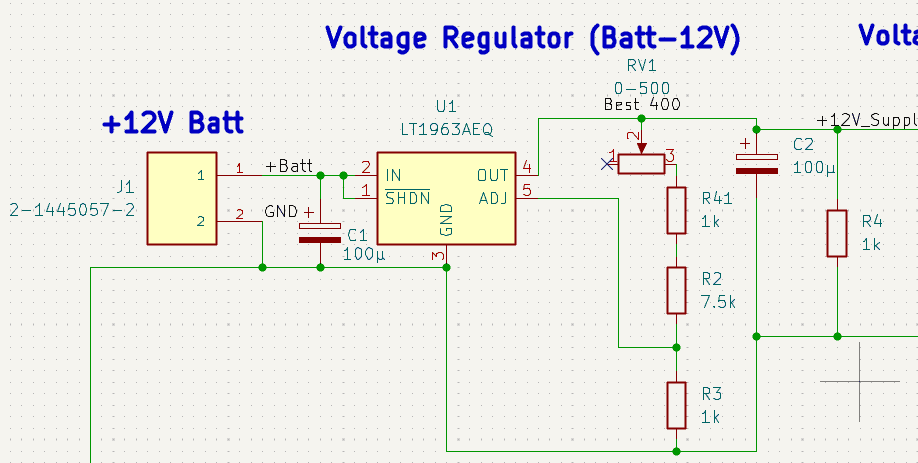
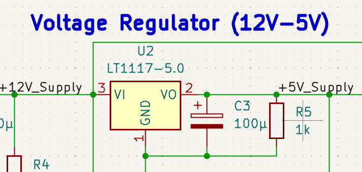
- Finalized the regulated supplies after defining the functional loads and rail requirements.
- Converted the validated simulation into exact-component KiCad schematics for the 12 V and 5 V rails.
- Used an adjustable 12 V stage to preserve threshold accuracy despite manufacturing tolerances.
Step 7 – Integrate the safety architecture into a manufacturable PCB
After completing the functional schematic architecture and the targeted LTspice analyses, I integrated the circuit blocks into a hierarchical KiCad design.
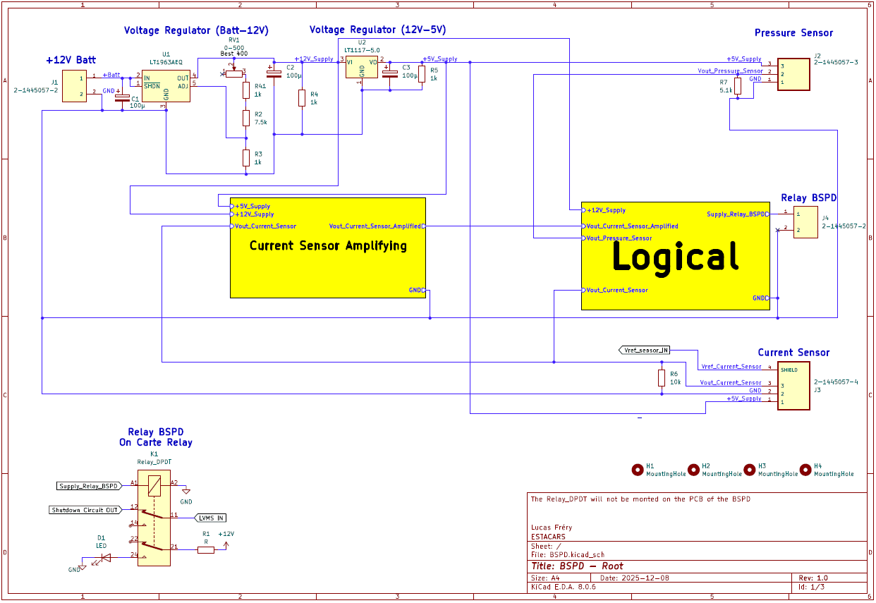
I assigned the final component references, footprints, and vehicle-compatible connectors while preserving traceability between the regulatory requirements and each hardware function.
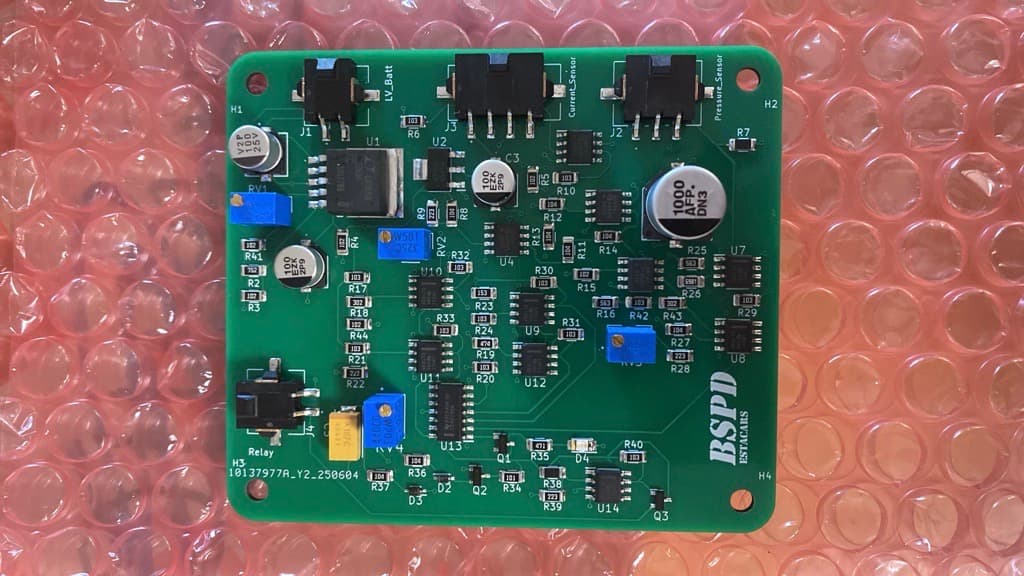
The resulting 85 mm × 70.5 mm PCB organizes the regulated supplies, current-signal conditioning, plausibility comparison, sensor-fault diagnostics, timing, and relay-control stages into identifiable functional areas. The vehicle connectors are positioned along the board edge, while calibration components and inspection interfaces remain accessible. Four mounting holes define the board's mechanical integration points.
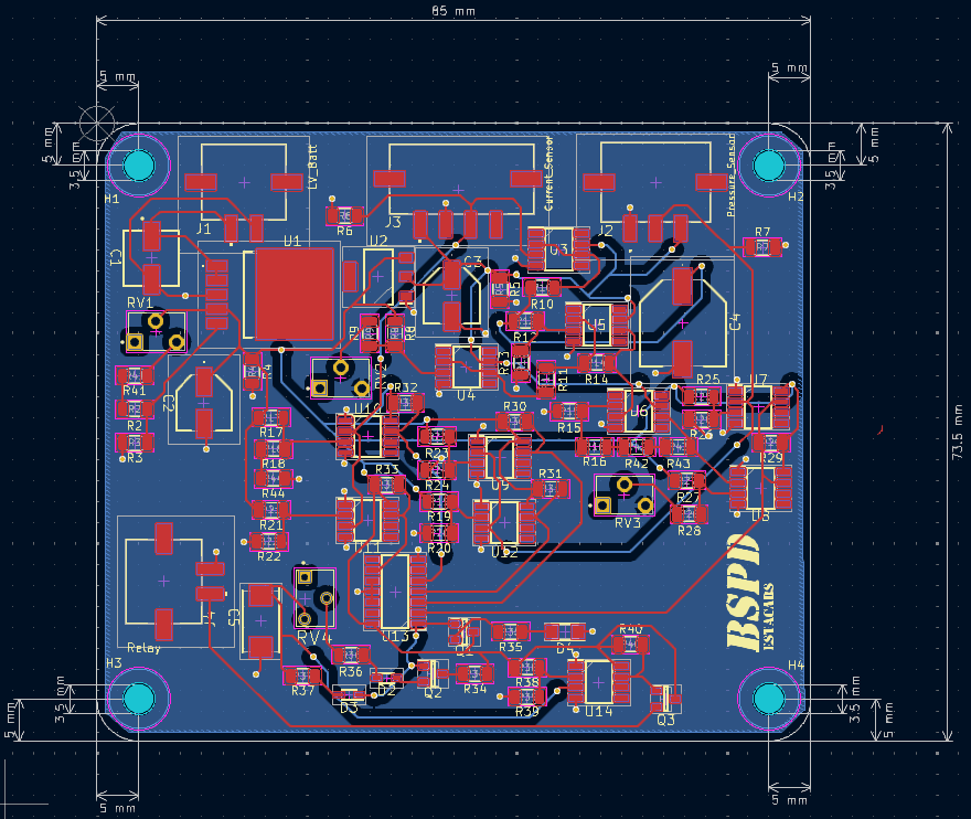
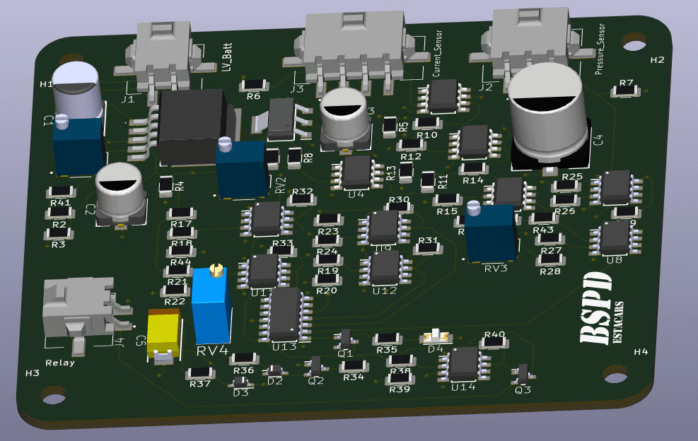
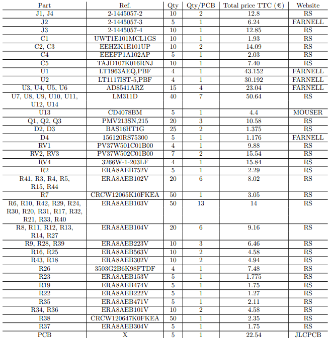
I used the KiCad 3D model to review component orientation, footprint compatibility, connector access, and assembly clearances before manufacturing. I also prepared the complete bill of materials; the project report estimates EUR 361.26 to source enough components and PCBs for three assemblies.
Step 8 – Execute the validation plan and qualify the BSPD in the vehicle
I began validation by creating a structured Excel test plan containing approximately 50 test cases. The matrix translated the applicable FSG 2025 rules and technical-inspection procedures into verifiable tests covering functional behavior, detection thresholds, timing, System Critical Signal faults, fail-safe operation, inspection interfaces, and SDC actuation. This created traceability between each technical requirement, its test method, the expected response, and the recorded result.
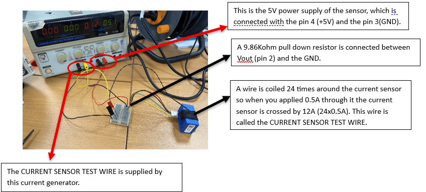
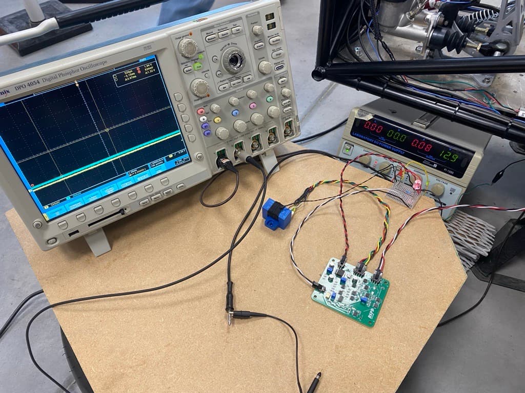
I first executed the plan at component and subsystem level, beginning with both System Critical Signals. The pressure-sensor channel was tested across its operating range and fault conditions. For the HASS 200-S current sensor, I used a conductor passing 24 times through the sensor aperture so that bench currents between 0 and 0.5 A reproduced vehicle-equivalent currents between 0 and 12 A. At the 12 A-equivalent point, I measured a 37.4 mV variation against the theoretical 37.5 mV result.
After validating both sensor channels, I connected the complete BSPD system to the vehicle with the low-voltage circuit energized. At this stage, the HV system did not need to produce the required propulsion current: more than 0.5 A was injected through the 24-turn test conductor to reproduce a current above the BSPD threshold. This configuration allowed the installed wiring, sensor interfaces, BSPD logic, relay output, and connection to the vehicle SDC to be exercised safely in the vehicle architecture.

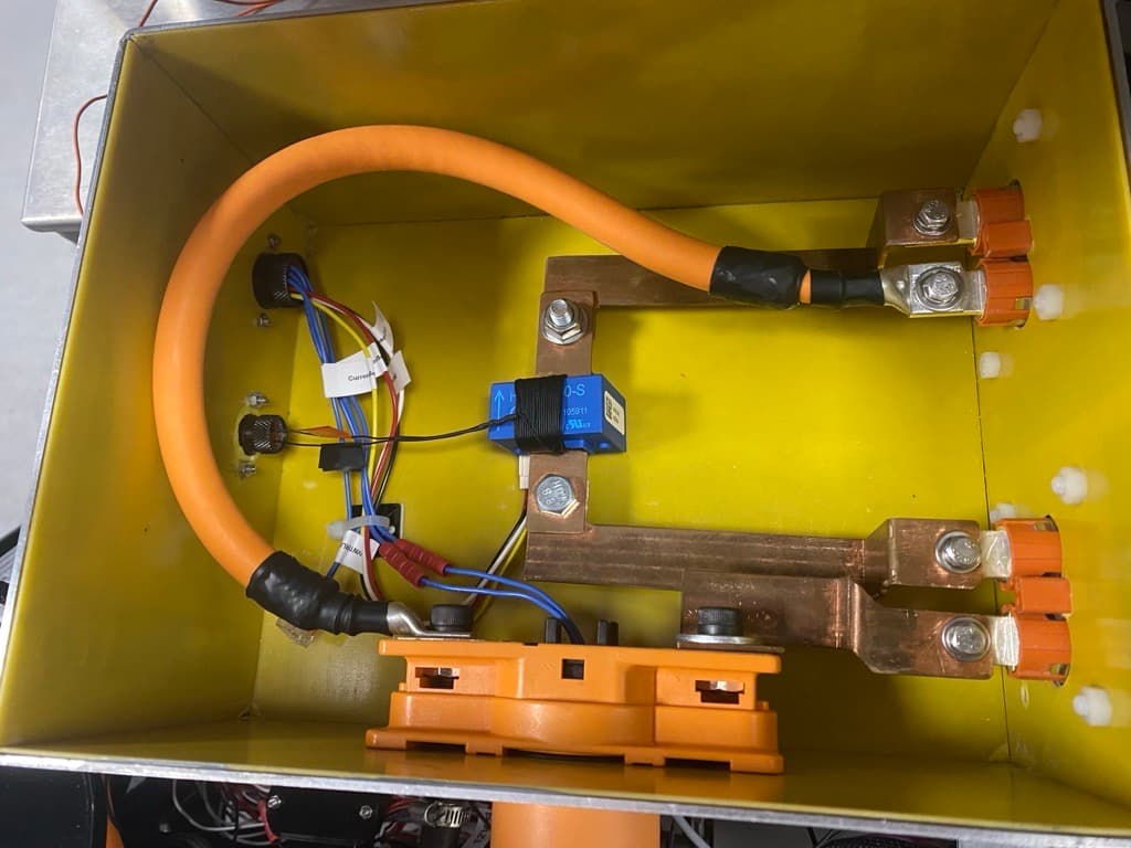
The HASS 200-S was then installed around the real high-voltage DC-link conductor. With the BSPD fully integrated, I repeated the complete test plan under representative operating conditions: the low-voltage and high-voltage systems were active, the BSPD was installed in its vehicle configuration, and the car was driven. This final campaign tested the safety function using the real brake-pressure and DC-link current signals rather than simulated current injection.
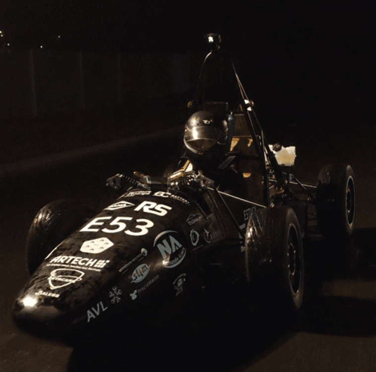
Repeating the same requirement-based test plan at bench, integrated low-voltage, and fully operational vehicle levels provided progressive evidence from individual sensor behavior to complete-system performance. The BSPD was fully validated in the driving vehicle against the defined functional and technical requirements, including its interaction with the SDC and its fail-safe response.
The resulting validation record provides traceable evidence against the FSG 2025 rulebook and technical-inspection sheets. It demonstrates that the manufactured BSPD, its sensors, vehicle wiring, shutdown interface, and installed behavior were tested as one complete safety system—not only as isolated electronic functions.
- Approximately 50 traceable test cases derived from the FSG 2025 rules and technical-inspection sheets.
- Both System Critical Signal channels validated before complete-system integration.
- Complete BSPD and SDC interface tested in the vehicle with the low-voltage system active and simulated current injection.
- Full test plan repeated with the BSPD installed, the HV system active, and the vehicle driving.
- BSPD fully validated in the operational vehicle against the defined functional and technical requirements.
Results
The project delivered a manufactured, standalone BSPD that was integrated into the Formula Student vehicle and fully validated from bench testing to operation with the HV system active and the car driving.
Key outcomes
Delivered safety function
- Non-programmable hardware monitors brake pressure and DC-link current, detects sensor faults, and opens the SDC through fail-safe logic.
- Brake and current thresholds were implemented at approximately 20.75 bar and 11.52 A.
- The nominal 250 ms persistence delay remains below the 500 ms maximum reaction time.
Manufactured and verified hardware
- The complete schematic, regulated supplies, analog logic, and 85 mm × 70.5 mm PCB were designed, assembled, and integrated into the vehicle.
- The current-sensor response matched theory within 1 mV across the documented test points.
Vehicle-level validation
- Approximately 50 tests were derived from the FSG 2025 rules and technical-inspection sheets.
- Both sensors and the complete BSPD were validated before and after vehicle integration.
- The full test plan was repeated successfully with the HV system active and the car driving.