
EMI Diagnosis · Vehicle Integration
Resolving EMI on an RS-485 BMS Link
Oscilloscope-led diagnosis of inverter-induced interference, followed by hardware changes that restored reliable communication during high-voltage operation.
VALIDATED
Role
Hardware & Embedded Systems Engineer
Project
ESTACARS Formula Student - France
Period
September 2023 – January 2026
Problem
During high-voltage power delivery, the BMS RS-485 link became unstable and stopped delivering battery voltage, temperature, and current data. The vehicle safety system correctly reacted to the missing BMS communication by opening the Accumulator Isolation Relays (AIRs), but the repeated unintended shutdowns prevented reliable vehicle operation.
Because the link behaved normally outside these operating conditions, the investigation had to distinguish between a software or protocol failure and a physical-layer disturbance created by the powertrain. The work therefore focused on reproducing the fault, measuring both RS-485 conductors during HV operation, identifying the interference signature, and implementing a mitigation that preserved the communication waveform.
Core requirements
- Reproduce the communication failure under controlled high-voltage operating conditions.
- Measure the RS-485 physical layer and correlate electrical disturbances with BMS communication errors.
- Identify the dominant interference frequency and its relationship with powertrain operation.
- Attenuate the interference without excessively degrading the RS-485 differential amplitude or edge timing.
- Restore continuous BMS sensor data and eliminate AIR openings caused by communication loss.
Solution
I instrumented the RS-485 link with a Tektronix DPO4054 oscilloscope while monitoring the BMS diagnostic logs and repeatedly operating the high-voltage system. The disturbed captures contained repetitive high-frequency spikes at approximately 25 kHz. Their appearance during power delivery and correspondence with the inverter IGBT switching frequency strongly indicated EMI coupling from the powertrain into the communication path.
I developed a passive RC filtering solution for the RS-485 path and tuned it experimentally. Each iteration balanced high-frequency attenuation against differential-signal amplitude, transition time, and reliable frame reception. I also reviewed the grounding and shielding arrangement to reduce the available coupling paths.
After implementing the selected filter network in the accumulator wiring, I repeated the same high-voltage operating sequence. The filtered waveform retained clearly distinguishable communication states, BMS sensor messages remained available, and communication loss no longer triggered unintended AIR opening during the tested conditions.
Platform capabilities
- Oscilloscope-based diagnosis under representative HV operation.
- Frequency correlation between the measured interference and inverter switching.
- Passive RC mitigation tuned against both noise attenuation and signal integrity.
- Grounding and shielding improvements within the accumulator installation.
- Before-and-after validation using waveforms, BMS logs, and vehicle behavior.
Method
Step 1 — Reproduce and isolate the HV-dependent failure
I reproduced the fault with the accumulator, BMS, and RS-485 wiring installed in their operating configuration. Communication remained stable before power delivery, but valid BMS messages were lost when the powertrain became active. Repeating the operating sequence produced the same behavior, establishing a clear relationship between powertrain operation and the communication failure.
The failure was identified through a consistent event chain: voltage, temperature, and current messages stopped arriving, the diagnostic logs reported lost BMS communication, and the safety system opened the AIRs because valid battery data was no longer available. This made a permanent protocol or software defect less likely and provided a repeatable test condition for the physical-layer measurements performed in Step 2.
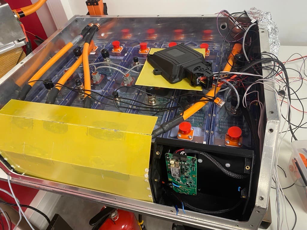
- Reproduced the same communication failure across repeated powertrain operating sequences.
- Tracked the failure from missing BMS sensor messages to diagnostic errors and the resulting AIR opening.
Step 2 — Measure and correlate the interference signature
I monitored both conductors of the RS-485 pair with a Tektronix DPO4054 oscilloscope while recording BMS diagnostic messages and repeating the powertrain operating sequence established in Step 1. This allowed the conductor voltages, communication errors, and inverter operating state to be compared during the same failure event.
The captures showed fast transient spikes recurring at approximately 25 kHz while the inverter was operating. This repetition rate matched the inverter IGBT switching frequency, and the disturbance appeared during the same events as the loss of BMS messages. The combined electrical and functional evidence identified inverter-generated EMI as the likely source of the RS-485 communication failure, rather than an independent application-layer fault.
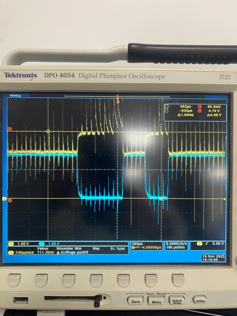
- Captured transient interference on both RS-485 conductors during communication loss.
- Measured an approximately 25 kHz repetition rate matching the inverter IGBT switching frequency.
- Correlated the physical-layer disturbance with BMS communication errors.
Step 3 — Design and tune the RS-485 filter
Based on the measured transient waveform and its effect on the RS-485 communication levels, I developed a first-order RC filter to attenuate the interference. The design had to reduce the transient amplitude while preserving sufficient differential voltage, transition speed, and timing margin for reliable frame detection.
I evaluated candidate component values under the same inverter operating conditions used during diagnosis. After each iteration, I compared the conductor waveforms, BMS messages, and diagnostic errors to determine whether the interference was reduced without excessively degrading the communication signal. In parallel, I reviewed the grounding and shielding arrangement to reduce the coupling paths rather than relying on filtering alone.
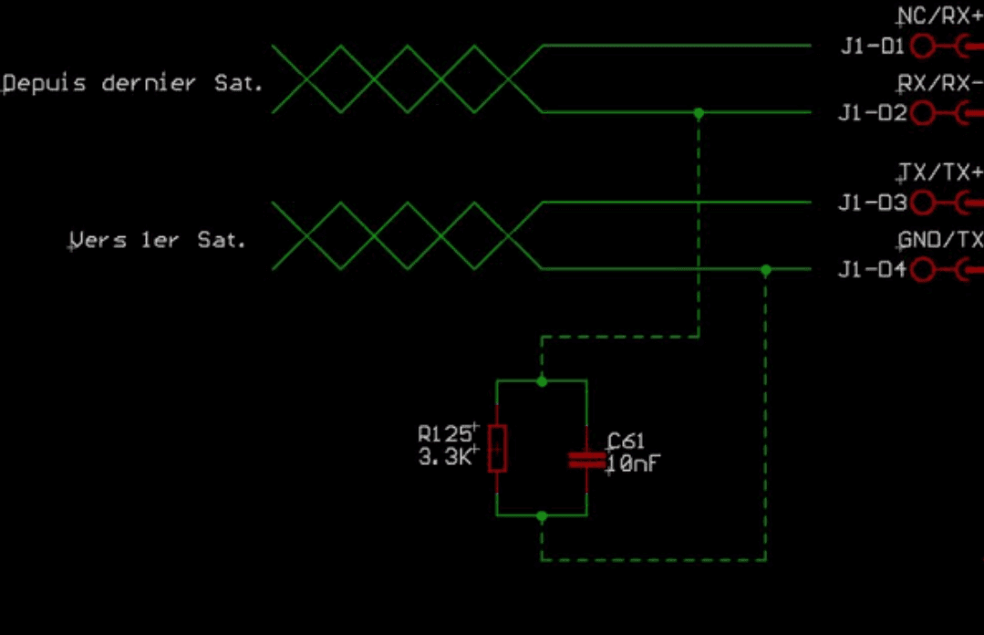
- Evaluated candidate RC values under the same inverter operating conditions used during diagnosis.
- Balanced transient attenuation against differential amplitude and edge timing.
- Verified each iteration using oscilloscope captures and BMS diagnostic messages.
- Reviewed grounding and shielding to reduce the underlying interference-coupling paths.
Step 4 — Integrate the filter into the accumulator
I integrated the selected RC network into the accumulator communication wiring while keeping the added conductor lengths short to limit parasitic effects and additional interference pickup. The connections were soldered, mechanically secured, and visually inspected before the system was energized.
I also reviewed and adjusted the local grounding and shielding arrangement to reduce interference coupling into the communication path. After inspection, the completed installation was prepared for validation using the same powertrain operating sequence and measurement points established during diagnosis.
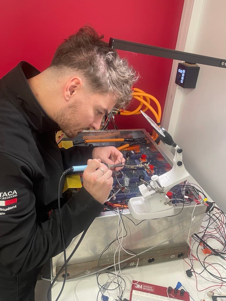
- Integrated the selected RC network into the accumulator communication wiring.
- Kept added conductor lengths short and mechanically secured the installation.
- Reviewed the completed hardware before high-voltage validation.
- Prepared the system for testing under the original failure conditions.
Step 5 — Validate electrical and system-level performance
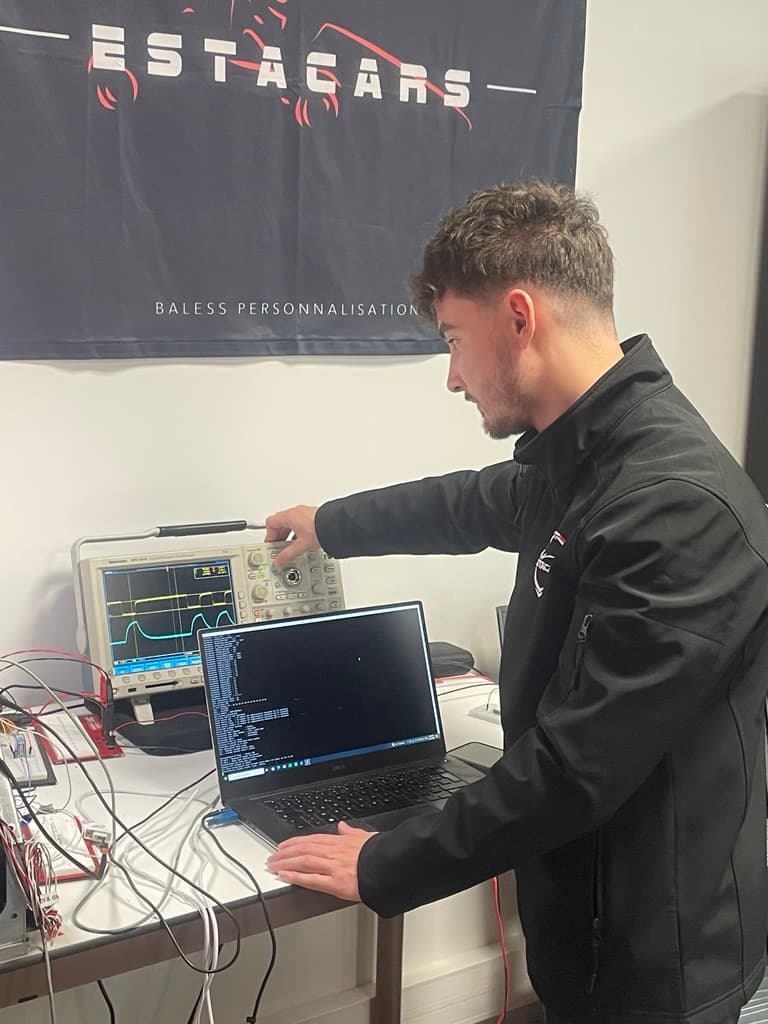
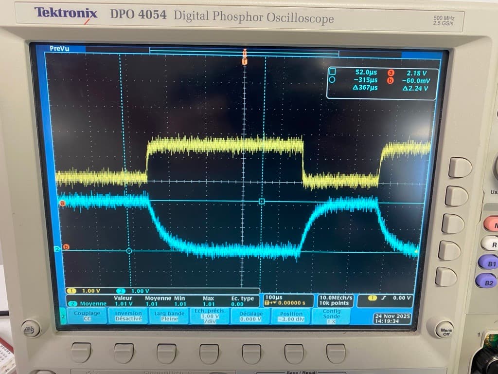
I repeated the original powertrain operating sequence using the same oscilloscope connection points and BMS monitoring established during diagnosis. Comparing the pre- and post-mitigation captures showed that the repetitive transient bursts were substantially attenuated while the RS-485 communication levels remained clearly distinguishable.
The improvement was then confirmed at system level throughout the tested sequence: BMS voltage, temperature, and current messages remained available, the diagnostic communication errors no longer appeared, and communication loss did not cause an unintended AIR opening.
- Repeated the original failure conditions using the same measurement points.
- Compared pre- and post-mitigation waveforms under equivalent operating conditions.
- Confirmed that BMS sensor data remained available without communication errors.
- Verified that no communication-related AIR opening occurred during the tested sequence.
Results
Under the same powertrain conditions used to reproduce the original fault, the installed RC filter substantially reduced the transient interference while preserving distinguishable RS-485 communication levels. BMS sensor data remained available, no communication errors were observed, and no communication-related AIR opening occurred during the validation sequence.
Validated outcomes
Interference source identified
- Communication loss was repeatedly reproduced during powertrain operation.
- Transient interference recurring at approximately 25 kHz matched the inverter IGBT switching frequency.
- The physical-layer disturbance coincided with the loss of BMS messages.
Mitigation designed and integrated
- A first-order RC filter was tuned against interference attenuation and RS-485 signal integrity.
- The selected filter was integrated into the accumulator communication wiring.
- The grounding and shielding arrangement was reviewed and adjusted to reduce interference coupling.
System behavior validated
- Post-mitigation captures showed substantially reduced transient interference.
- RS-485 communication levels remained distinguishable and BMS sensor data remained available.
- No communication errors or communication-related AIR openings occurred during the tested sequence.